Pipe Coupling Dimensions – Socket Weld & Threaded Couplings
Socket Weld Coupling Dimensions
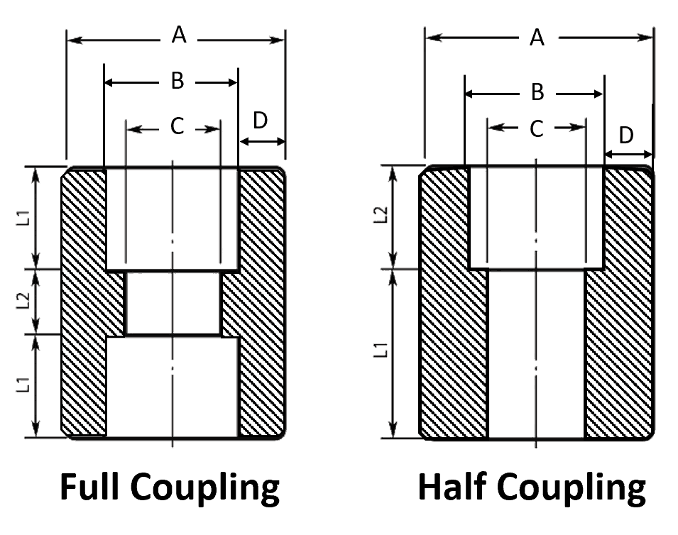
| NOMINAL PIPE SIZE | OUTER DIAMETER | SOCKET BORE DIAMETER | BORE DIAMETER OF FITTINGS | BORE DIAMETER OF FITTINGS | BORE DIAMETER OF FITTINGS | WALL THICKNESS # 3000 | WALL THICKNESS # 3000 | WALL THICKNESS # 6000 | WALL THICKNESS # 6000 | WALL THICKNESS # 9000 | WALL THICKNESS # 9000 | FULL COUPLING | FULL COUPLING | HALF COUPLING | HALF COUPLING |
|---|---|---|---|---|---|---|---|---|---|---|---|---|---|---|---|
| Inch. | A | B | C – 3000 | C – 6000 | C – 9000 | D | D | D | D | D | D | L1 | L2 | L1 | L2 |
| Maximum Minimum | Maximum Minimum | Maximum Minimum | Maximum Minimum | Average | Minimum | Average | Minimum | Average | Minimum | ||||||
| 1/8 | B+D | 11.2 10.8 | 7.6 6.1 | 4.8 3.2 | 3.18 | 3.18 | 3.96 | 3.43 | 9.5 | 6.5 | 9.5 | 16.0 | |||
| 1/4 | B+D | 14.6 14.2 | 10.0 8.5 | 7.1 5.6 | 3.78 | 3.30 | 4.6 | 4.01 | 9.5 | 6.5 | 9.5 | 16.0 | |||
| 3/8 | B+D | 18.0 17.6 | 13.3 11.8 | 9.9 8.4 | 4.01 | 3.50 | 5.03 | 4.37 | 9.5 | 6.5 | 9.5 | 17.5 | |||
| 1/2 | B+D | 22.2 21.8 | 16.6 15.0 | 12.5 11.0 | 7.2 5.6 | 4.67 | 4.09 | 5.97 | 5.18 | 9.35 | 8.18 | 9.5 | 9.5 | 9.5 | 22.5 |
| 3/4 | B+D | 27.6 27.2 | 21.7 20.2 | 16.3 14.8 | 11.8 10.3 | 4.90 | 4.27 | 6.96 | 6.04 | 9.78 | 8.56 | 12.5 | 9.5 | 12.5 | 24.0 |
| 1 | B+D | 34.3 33.9 | 27.4 25.9 | 21.5 19.9 | 16.0 14.4 | 5.69 | 4.98 | 7.92 | 6.93 | 11.38 | 9.96 | 12.5 | 12.5 | 12.5 | 28.5 |
| 1 1/4 | B+D | 43.1 42.7 | 35.8 34.3 | 30.2 28.7 | 23.5 22.0 | 6.07 | 5.28 | 7.92 | 6.93 | 12.14 | 10.62 | 12.5 | 12.5 | 12.5 | 30.0 |
| 1 1/2 | B+D | 49.2 48.8 | 41.6 40.1 | 34.7 33.2 | 28.7 27.2 | 6.35 | 5.54 | 8.92 | 7.8 | 12.7 | 11.12 | 12.5 | 12.5 | 12.5 | 32.0 |
| 2 | B+D | 61.7 61.2 | 53.3 51.7 | 43.6 42.1 | 38.9 37.4 | 6.93 | 6.04 | 10.92 | 9.5 | 13.84 | 12.12 | 16.0 | 19.0 | 16.0 | 41.0 |
| 2 1/2 | B+D | 74.4 73.9 | 64.2 61.2 | 8.76 | 7.67 | 16.0 | 19.0 | 16.0 | 43.0 | ||||||
| 3 | B+D | 90.3 89.8 | 79.4 76.4 | 9.52 | 8.30 | 16.0 | 19.0 | 16.0 | 44.5 | ||||||
| 4 | B+D | 103.8 100.7 | 103.8 100.7 | 10.69 | 9.35 | 16.0 | 19.0 | 16.0 | 48.0 | ||||||
| All Dimensions are in mm | |||||||||||||||
Threaded Coupling Dimensions
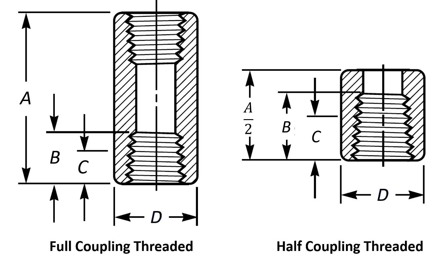
| NOMINAL PIPE SIZE | END TO END | MINIMUM LENGTH OF THREAD | OUTSIDE DIAMETER | |||
|---|---|---|---|---|---|---|
| Inch. | Full Coupling | Half Coupling | # 3000 | # 6000 | ||
| A | A/2 | B | C | D | D | |
| 1/8 | 32 | A/2 | 6.7 | 6.4 | 16 | 22 |
| 1/4 | 35 | A/2 | 10.2 | 8.1 | 19 | 25 |
| 3/8 | 38 | A/2 | 10.4 | 9.1 | 22 | 32 |
| 1/2 | 48 | A/2 | 13.6 | 10.9 | 28 | 38 |
| 3/4 | 51 | A/2 | 13.9 | 12.7 | 35 | 44 |
| 1 | 60 | A/2 | 17.3 | 14.7 | 44 | 57 |
| 1 1/4 | 67 | A/2 | 18 | 17 | 57 | 64 |
| 1 1/2 | 79 | A/2 | 18.4 | 17.8 | 64 | 76 |
| 2 | 86 | A/2 | 19.2 | 19 | 76 | 92 |
| 2 1/2 | 92 | A/2 | 28.9 | 23.6 | 92 | 108 |
| 3 | 108 | A/2 | 30.5 | 25.9 | 108 | 127 |
| 4 | 121 | A/2 | 33 | 27.7 | 140 | 159 |
| All Dimensions are in mm | ||||||
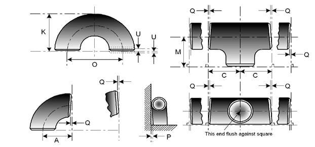
Pipe Fittings Dimensions Tolerance as per ASME B16.9
| NOMINAL PIPE SIZE | ALL FITTINGS | ALL FITTINGS | ALL FITTINGS | ELBOWS AND TEES | 180 DEG RETURN BENDS | 180 DEG RETURN BENDS | 180 DEG RETURN BENDS | REDUCERS | CAPS |
|---|---|---|---|---|---|---|---|---|---|
| NPS | O.D. at Bevel (1), (2) | I.D. at End (1), (3), (4) | Wall Thickness (3) | Centre-to-End Dimension A,B,C,M | Centre-to-Centre O | Back-to-Face K | Alignment of Ends U | Overall Length H | Overall Length E |
| ½ to 2½ | 0.06 -0.03 | 0.03 | Not less than 87.5% of nominal thickness | 0.06 | 0.25 | 0.25 | 0.03 | 0.06 | 0.12 |
| 3 to 3 ½ | 0.06 | 0.06 | 0.06 | 0.25 | 0.25 | 0.03 | 0.06 | 0.12 | |
| 4 | 0.06 | 0.06 | 0.06 | 0.25 | 0.25 | 0.03 | 0.06 | 0.12 | |
| 5 to 8 | 0.09 -0.06 | 0.06 | 0.06 | 0.25 | 0.25 | 0.03 | 0.06 | 0.25 | |
| 10 to 18 | 0.16 -0.12 | 0.12 | 0.09 | 0.38 | 0.25 | 0.06 | 0.09 | 0.25 | |
| 20 to 24 | 0.25 -0.19 | 0.19 | 0.09 | 0.38 | 0.25 | 0.06 | 0.09 | 0.25 | |
| 26 to 30 | 0.25 -0.19 | 0.19 | 0.12 | … | … | … | 0.19 | 0.38 | |
| 32 to 48 | 0.25 -0.19 | 0.19 | 0.19 | … | … | … | 0.19 | 0.38 |
| NOMINAL PIPE SIZE NPS | ANGULARITY TOLERANCES | ANGULARITY TOLERANCES | ALL DIMENSIONS ARE GIVEN IN INCHES. TOLERANCES ARE EQUAL PLUS AND MINUS EXCEPT AS NOTED. |
|---|---|---|---|
| Off Angle Q | Off Plane P | (1) Out-of-round is the sum of absolute values of plus and minus tolerance. (2) This tolerance may not apply in localized areas of formed fittings where increased wall thickness is required to meet design requirements of ASME B16.9. (3) The inside diameter and the nominal wall thicknesses at ends are to be specified by the purchaser. (4) Unless otherwise specified by the purchaser, these tolerances apply to the nominal inside diameter, which equals the difference between the nominal outside diameter and twice the nominal wall thickness. | |
| ½ to 4 | 0.03 | 0.06 | |
| 5 to 8 | 0.06 | 0.12 | |
| 10 to 12 | 0.09 | 0.19 | |
| 14 to 16 | 0.09 | 0.25 | |
| 18 to 24 | 0.12 | 0.38 | |
| 26 to 30 | 0.19 | 0.38 | |
| 32 to 42 | 0.19 | 0.50 | |
| 44 to 48 | 0.18 | 0.75 |